The Two Most Commonly Used PCL INPUT AND OUTPUT METHODS: SWITCH AND ANALOG
The amount of switching and analog is to learn the maximum number of input and output methods in the initial use of PLC. What is the switch? What is an analog? This problem must be clarified.
When the pressure is high, the two contacts of C and B are closed, the output pressure is high, and the pressure is low when the pressure is low, and the two contacts are closed, and the output pressure is low. With such a signal, the pressure signal of the place is realized, and the electrical control cabinet from the distance is high to participate in automatic remote control, where C and B are a switch amount, C and A are also a switch. So a switch contact is a switch, and its characteristics are either disconnected at the same time. Turn on is 1, representing a signal, disconnect is 0, and the representative has no signal. This is the so-called switching signal.
Although the pressure gauge can pass the pressure signal to the distant, it is transmitted only a signal such as a pressure, and cannot know how much the real-time pressure value is.
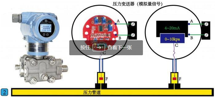
The inside of the pressure transmitter is a circuit board, and a circuit board is connected to a pressure sensor F. Its working principle is that the pressure sensor f transmits the detected pressure to the Circuit board. After the detection signal enters the circuit board, converting this pressure signal into a current signal by the conversion and calculation of the circuit board, two of the current signals from A and B. Point output. On the right side of the figure is a schematic of the conversion process, it can convert a 0-10 kPa pressure signal into a 4-20mA current signal, output from two points of A and B. At this time, we say that the two points of the A and B have been an analog signal. The simulation signal is characterized by its value in a range of values.
Let's take a look at how the analog signal is transmitted.

A pressure transmitter of a range of 0-10kpa is installed on our pipe, the B point of the power supply positive electrode, and the negative electrode is connected in series to the A point of the pressure transmitter, and hit the multimeter to current. When the pressure of the pressure transmitter C is 5 kPa, the current reading of the multimeter is 12 mA. It is exactly the intermediate value of the current signal of 4-20mA, and 5kpa is also the intermediate value of the 0-10 kPa pressure value.
When the pressure of the pressure transmitter C is 10 kPa, the current reading of the multimeter is exactly 20 mA. Such a 0-10 kPa pressure value corresponds to the current signal value of 4-20mA, as long as we extract this 4-20mA current signal value through a receiving device in the distance, you can know the pressure on the ground by certain calculations. What is the value.
Why convert pressure signals into 4-20mA current signals, not 0-20mA current signal or voltage signal of 0-10V?
1.0-10V voltage signals are easily electromagnetic interference in the outside, especially if the cable length is long and disturbed.
2. If the 0-20mA current signal cannot be judged that the current signal is 0 mA, it is normal 0mA due to the cable disconnection caused by the cable disconnection, or the pressure itself is 0 mA output from 0KPa.
This is the most basic method of use, the left is the switch, the right is analog, and the different signal types are connected to the different inputs of the PLC.


